Rtl Code For 4 Bit Counter With Asynchronous Active Low Reset : Behavioral Modeling Of Sequential Logic Springerlink / Lets start with simple counter code in rtl.
Get link
Facebook
X
Pinterest
Email
Other Apps
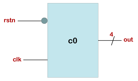
Rtl Code For 4 Bit Counter With Asynchronous Active Low Reset : Behavioral Modeling Of Sequential Logic Springerlink / Lets start with simple counter code in rtl.. 4 bit binary asynchronous reset counter verilog code. Introducing edge spartan 6 fpga development board! Verilog code for d flip flop is presented in this project. 4 bit down counter will count numbers from 15 to 0, downwards. O input clear (asynchronous reset / negedge signal)o input preset (synchronous and active low singal)o input load_cnt (value gets loaded when !preset)o output count (output count value) is this question part of your assignment?
Verilog code for d flip flop is presented in this project. I read about asynchronous and synchronous reset and i think i got hold of it but while implementing the same with verilog i am not able to understand a line of code which i saw on this website. A 4 bit asynchronous down counter is shown in above diagram. Download the files used in this example: I am modelling a 4 bit register with enable and asynchronous reset.
Verilog 4 Bit Counter Javatpoint from static.javatpoint.com Verilog code for d flip flop is presented in this project. (asynchronous reset / negedge signal) o input preset (synchronous and active low singal) o input load_cnt (value gets loaded when !preset) o output count (output count value) 4 bit down counter will count numbers from 15 to 0, downwards. In the asynchronous reset code why are we using the always @ (posedge clk or posedge reset) instead of using always @ (posedge clk ). How to design a decade counter? Its operating frequency is much higher than the same range asynchronous counter. Counter example % ˙ % ! It is simple modification of the up counter.
We aim to offer the best fpga.
The output of q0 and q1 undergo an and operation and applies to q2. Synthesis tools detect counter designs in hdl code and infer lpm_counter megafunction. This page of verilog source code section covers 4 bit binary synchronous reset counter verilog code.the block diagram and truth table of 4 bit binary synchronous reset counter verilog code is also mentioned. Counter example % ˙ % ! I am modelling a 4 bit register with enable and asynchronous reset. Always @(posedge clock or negedge reset). Reset circuit helps to keep the fpga in to known state. We will use asynchronous reset here in the example. Entity dff is port (d : 4 bit binary synchronous reset counter verilog code. A decade counter counts ten events or till the number 10 and then resets to zero. // just the code snippet below. Introducing edge spartan 6 fpga development board!
Reset circuit helps to keep the fpga in to known state. A 4 bit asynchronous down counter is shown in above diagram. Verilog for 4 bit counter code and testbench 1. In the asynchronous reset code why are we using the always @ (posedge clk or posedge reset) instead of using always @ (posedge clk ). They are synchronous and asynchronous reset.
4 Bit Counter from www.chipverify.com They are synchronous and asynchronous reset. Verilog code for d flip flop is presented in this project. Always @(posedge clock or negedge reset). It is simple modification of the up counter. Download the files used in this example: Generally, the asynchronous reset is active low, the other synchronous logic can be either active high or low. A decade counter counts ten events or till the number 10 and then resets to zero. Synthesis tools detect counter designs in hdl code and infer lpm_counter megafunction.
Vhdl code for d flip flop is presented in this project.
Some fpgas have a recommendation about the usage but it is technology dependent. Here is my design and testbench. Synthesis tools detect counter designs in hdl code and infer lpm_counter megafunction. 4 bit binary asynchronous reset counter verilog code. 3 — 16 march 2021 product data sheet 1. This page of verilog source code section covers 4 bit binary synchronous reset counter verilog code.the block diagram and truth table of 4 bit binary synchronous reset counter verilog code is also mentioned. Introducing edge spartan 6 fpga development board! The output of q0 and q1 undergo an and operation and applies to q2. 4 bit binary synchronous reset counter verilog code. Counter example % ˙ % ! § synthesize johnson counter connect with a professional writer in 5 simple steps please provide as many details about your writing struggle as possible academic level of your paper type of paper essay (any type) essay (any type) article (any type) assignment … It is simple modification of the up counter. Verilog code for d flip flop is presented in this project.
Generally, the asynchronous reset is active low, the other synchronous logic can be either active high or low. The always block is executed whenever the clock transitions from 0 to 1, which signifies a positive edge or a rising edge. In the asynchronous reset code why are we using the always @ (posedge clk or posedge reset) instead of using always @ (posedge clk ). A 4 bit asynchronous down counter is shown in above diagram. I am new to verilog and having a bit of trouble getting along with it.
Fifo Buffer Module With Watermarks Verilog And Vhdl Logic Engineering And Component Solution Forum Techforum Digi Key from aws1.discourse-cdn.com Synthesis tools detect counter designs in hdl code and infer lpm_counter megafunction. I am modelling a 4 bit register with enable and asynchronous reset. This page of verilog source code section covers 4 bit binary asynchronous reset counter verilog code.the block diagram and truth table of 4 bit binary asynchronous reset counter verilog code is also mentioned. A decade counter counts ten events or till the number 10 and then resets to zero. 4 bit down counter will count numbers from 15 to 0, downwards. Its operating frequency is much higher than the same range asynchronous counter. I am new to verilog and having a bit of trouble getting along with it. We aim to offer the best fpga.
4 bit binary asynchronous reset counter verilog code.
The output of q0 and q1 undergo an and operation and applies to q2. Here is my design and testbench. A 4 bit asynchronous down counter is shown in above diagram. Some fpgas have a recommendation about the usage but it is technology dependent. O input clear (asynchronous reset / negedge signal)o input preset (synchronous and active low singal)o input load_cnt (value gets loaded when !preset)o output count (output count value) is this question part of your assignment? Always @(posedge clock or negedge reset). Verilog for 4 bit counter code and testbench 1. § synthesize johnson counter connect with a professional writer in 5 simple steps please provide as many details about your writing struggle as possible academic level of your paper type of paper essay (any type) essay (any type) article (any type) assignment … We aim to offer the best fpga. 4 bit binary synchronous reset counter verilog code. Its operating frequency is much higher than the same range asynchronous counter. I am new to verilog and having a bit of trouble getting along with it. If reset is low at the clock's positive edge, then output is reset to a.
If reset is low at the clock's positive edge, then output is reset to a rtl code. Design 4bit up counter with.


Comments
Post a Comment